Page 12 of 256
Re: FAULTY ELM 327 INTERFACES DE-MYSTIFIED (READ HERE)
Posted: 29 Jul 2011, 09:05
by alfa156sarajevo
mattydr67 wrote:Hi m8
Yes remove the resistor R04 like Mr. Alfa156sarajevo said and all will be ok.
You're interface will start to work on CAN
Good luck
I agree with
mattydr67! Remove resistor R04 and you ELM327 interface should work...
Cheers,

Re: FAULTY ELM 327 INTERFACES DE-MYSTIFIED (READ HERE)
Posted: 29 Jul 2011, 16:56
by osmangdk
Hi,I'm again...

((((
ABS,ASR,VDC not connect ELM327. I added Photo .
But,ELM connect to Body computer as finally.(a situation a little better.)
Do you think I take a new wire.
Do you think,I taking to VAGCOM cable for ABS,ASR,VDC.
Re: FAULTY ELM 327 INTERFACES DE-MYSTIFIED (READ HERE)
Posted: 29 Jul 2011, 19:05
by mattydr67
M8 for ABS you need to solder pin 7 and pin 1 together.
The ABS in your car it is not on CAN it is an K-line
You can connect to your engine ECU?
Re: FAULTY ELM 327 INTERFACES DE-MYSTIFIED (READ HERE)
Posted: 29 Jul 2011, 20:27
by osmangdk
I know. Multiecuscan interface types, choose K-line interface. This right?
I do ELM1 (1-7-9-12 solder).Add the photos.Is there anything else?
Re: FAULTY ELM 327 INTERFACES DE-MYSTIFIED (READ HERE)
Posted: 30 Jul 2011, 06:26
by mattydr67
Hey
What are you did there mate?
It is wrong
Unsolder it because thaat aren't the pins that you think there are.
You solder pin 1 with pin 7 and with pins 13 and pin 16. This wrong
Pins 12 and pin 9 are in the other side
The counter starts under the pin 1
I mean under pin 1 is pin 9 and under pin 8 is pin 16
In your pics pin one and pin 7 are solder well but unsolder pin 7 to 16 (9 in your pics )and pin 13 ( 12 in your pics )
Good luck and take care
Re: FAULTY ELM 327 INTERFACES DE-MYSTIFIED (READ HERE)
Posted: 30 Jul 2011, 07:31
by Alfaeddy
Hello
As has already written mattydr67, you have connected the wrong pins in the connector. Maybe you've already destroyed your interface. or your controller
In the picture you see how the pins are laid out, you should be careful.
Greetings Eddy
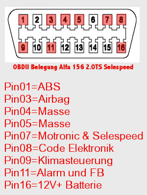
- obd-alfa.jpg (97.94 KiB) Viewed 12077 times
Re: FAULTY ELM 327 INTERFACES DE-MYSTIFIED (READ HERE)
Posted: 30 Jul 2011, 14:49
by osmangdk
Hi,thank you so much,all friends.I took your time.Forgive me.My English is not good.Sorry.
Photos took in the vertical . It looks like the mirror, see the reverse.
My Photos is bad.No mymachine for shooting macro...

So, I really solder 1,7,9,12 pins.
Finally,I take the regular photo on elm327.Added.
But, 9 pin and 12 pin unsolder.Now,I solder only 1 pin and 7 pin.
That is enough?
Do I need to do the new solder?
problem for fear of living.
I have not tried.What do I do?
again thank you...
Re: FAULTY ELM 327 INTERFACES DE-MYSTIFIED (READ HERE)
Posted: 30 Jul 2011, 21:28
by Alfaeddy
Hello
I do not understand how your image should be reversed?
Your joints are wrong
The symbol of me is not the socket of the connector
So imagine you put your plug into the OBD socket, and then counting
from the pins.
Auserd you can also connect the pins 8 and 11 and 13 still with.
Greetings Eddy
Re: FAULTY ELM 327 INTERFACES DE-MYSTIFIED (READ HERE)
Posted: 31 Jul 2011, 05:35
by mattydr67
Take a look here mate
Good luck
Re: FAULTY ELM 327 INTERFACES DE-MYSTIFIED (READ HERE)
Posted: 31 Jul 2011, 06:27
by osmangdk
See the photo this way.cable, such as the photo turned upside down.
May need to do another solder pin here?
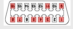
- obd-alfa.jpg (20.86 KiB) Viewed 12055 times